What is a Hotside Bypass Damper?

Hot Side Bypass Dampers help manage high VOC concentrations in RTOs.
A Hot Side Bypass Damper is an auxiliary system for Regenerative Thermal Oxidizers (RTOs) that allows the bypassing of the heat exchanger to manage high temperature conditions and maintain optimal performance.
Hot Side (Heat Exchanger) Bypass Damper
Regenerative Thermal Oxidizers (RTOs) typically operate at Lower Flammability Limit (LFL) levels below 5%. When LFL levels reach or exceed 5%, RTOs enter burner-free operation, also known as self-sustain mode. For LFL levels exceeding 7%, high temperature conditions necessitate the blending of outside air, bypassing the heat exchanger, or a combination of both. This allows the system to operate at up to 15% LFL.

Determining the Need for a Hot Side Bypass Damper (HSBD)
Once the solvent loading for the process is determined, KKI will calculate the necessity of the Hot Side Bypass Damper (HSBD). If required, the HSBD will include an internally insulated section to mix hot air from the combustion chamber with the RTO exhaust air. The entire exhaust stack will need to be constructed of stainless steel.
Features of the Hot Side Bypass Damper
The Hot Side Bypass Damper is an auxiliary system that can be purchased and added if required in the future. However, it is recommended to manufacture and install it as part of the initial equipment package to avoid additional mobilization charges later.
Design and Components
KKI designs and provides an internally insulated high VOC hot side bypass to bypass clean hot air directly into the exhaust stack, reducing the thermal efficiency of the oxidizer when VOC concentrations are high. Features of a Hot Side Bypass System includes:
- Sized for 25% of the total volume of the RTO
- Internally insulated ductwork connecting the combustion chamber to the hard refractory-lined damper assembly
- Castable, refractory-lined hot side bypass damper assembly with Inconel damper blade
- Electro pneumatic valve/actuator with internal limit switches
- Internally insulated ductwork connecting the combustion chamber to the hard refractory-lined damper assembly and carbon steel mix box located on the exhaust stack
- One internally insulated, carbon steel mixing box and additional stainless steel exhaust stack required above the mix box to discharge to the atmosphere
- Two 3" Ø test ports located 90 degrees apart on the exhaust stack
- Field installation, including all travel, labor, expenses, and rentals
- Hot side bypass damper assembly rated to 1,800°F
Benefits
- Efficiently manages high VOC concentrations
- Reduces thermal efficiency to prevent overheating
- Flexible installation options for future upgrades


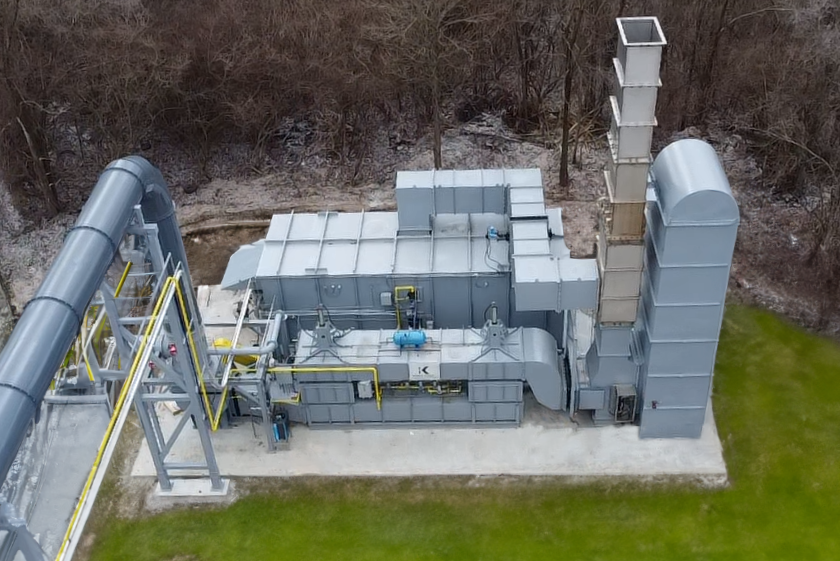
Custom Built Regenerative Thermal Oxidizer (RTO) Treating Food Packaging Emissions
Kono Kogs designed, fabricated & installed a custom RTO at a food packaging manufacturer